 Modern digital flow transmitters combine advanced multivariable sensing technology and built-in computational capabilities, allowing intelligent diagnosis of impulse-line blocking conditions that can lead to spurious readings as well as compromising efficient plant operation. Neil Hankey of Yokogawa Europe describes the latest developments in this technology, including extending its application to purge level measurements using dip-tube techniques.
Differential pressure (DP) flowmeters composed of an orifice plate, a DP transmitter, and other components are widely used in the refinery sector because they are reliable and require no wet calibration. The simple design of orifice plates and modern DP transmitters make them extremely reliable. However, the impulse lines which transmit process pressure to the DP transmitter (Fig 1) are vulnerable to blockages caused by factors such as fluid condensation, freezing, or corrosion. Impulse line blocking is a problem that must be addressed to ensure efficient operation and maintenance.
 Impulse-line blocking
Impulse-line blocking can be caused by various substances, including corrosion and debris, liquid freezing, liquid condensation or hydrates. Depending on the type of blocking substance, the blocking build-up rate varies. Liquid freezing or condensation leads to rapid blocking build-up, while blocking caused by corrosion progresses slowly. In order to predict the impulse-line blocking adequately, the diagnostic period has to be much shorter than the time taken for the blocking to build up.
To implement a predictive and effective diagnostic, it is necessary to provide a trend analysis of the blocking parameters, which enables corrective actions to be scheduled before the blocking triggers an unwanted large-scale process shutdown. The blocking parameters are related to statistically accumulated pressure fluctuations during a certain diagnostic period. Trend analysis of the blocking parameters is usually carried out and displayed in a higher-level plant asset management system.
Intelligent measurements
There has been a recent emergence of a new generation of DP transmitters equipped with digital silicon resonant sensors that can rapidly detect both static pressure and differential pressure, enabling the development of a diagnostic technique which detects fluctuations in these parameters (Fig 2). By using a digital communications network such as Fieldbus, operators can determine whether an impulse line at an installation site is blocked. This can significantly reduce maintenance workload and cost.
These new transmitters are multi-variable devices that can make three process measurements: differential pressure, absolute pressure and process temperature – and compensate for density changes using four distinct methods. An on-board flow computer is then able to derive mass flow with an accuracy of 0.1 per cent of reading, over a turndown of 10:1 on flow or 100:1 on differential pressure.
In auto-compensation mode, the transmitter utilises sophisticated algorithms to compensate for minor changes in the total flow solution. This includes changes such as the thermal expansion of the process pipe and primary measurement element, density changes within the flowing medium (whether that medium is a liquid, gas or vapour), plus a whole host of other related flow parameters.
The built-in sophistication in the mass flow transmitter is not accompanied by added complexity for the end-user, since flow configuration tools are now available to effectively free the end-user from these complexities by enabling quick, convenient configuration of transmitter parameters. Such tools even offer the ability to simulate flow conditions to validate the relevant parameters while offline. The configuration tool is based upon industry standard FDT/DTM (Field Device Tool/Device Type Manager) technology, which allows for a simplified and convenient visualisation of the various transmitter parameters. Rather than overwhelming the end-user with an endless list of individual parameters, it breaks these parameters down into logical groupings and sequences. A further advantage is the configuration tool can be used with both HART and Foundation Fieldbus communication technologies, in any compliant FDT frame application.
These intelligent transmitters can be used on liquids, gases or vapours, with a wide variety of primary elements, in standard, allocation or fiscal metering solutions and in natural gas applications requiring compliance with standards such as AGA3 and AGA8.
Impulse line blocking diagnosis
For impulse line blocking diagnosis applications, the significance of transmitters equipped with silicon resonant sensors is they can rapidly detect both static pressure and differential pressure, and can monitor process fluctuations at both the high and low sides without damping. These features, in conjunction with the diagnostic algorithms running within the transmitter’s built-in processor, enable the development of a diagnostic technique which uses the fluctuations in static and differential pressures to establish when and how blocking has occurred. With the addition of Fieldbus communications, centrally located operators can determine whether an impulse line at a specific installation site has been blocked. Such information can significantly reduce maintenance workload and cost, as well as providing other benefits:
• The system will inform operators or maintenance engineers that a blockage is forming in an impulse line before the process is disrupted.
• It becomes possible to predict when the impulse line will be blocked and suggests a corrective action, based on blockage thresholds.
• Blockage thresholds can be determined based on the blocking substance, flow-rate variations, and the time required to take corrective action.
The fluctuating components of differential and static pressures generally decrease when an impulse line is blocked. Fluctuating components are calculated as the square summation of the difference of differential and static pressures that are sampled at very short time intervals. The amplitudes of fluctuating components are derived from the root of the square summation. Since these components are affected by flow-rate changes, they are provided as fluctuation components through flow-rate compensation.
 Measurement results
Fig 3 shows the value of the fluctuating components when blocking occurs on the high side, low side and both sides. No blocking values are also shown. When both sides of impulse lines are blocked, all fluctuating components decrease. When one side of an impulse line is blocked, the corresponding fluctuating component decreases. In this case the fluctuating component of differential pressure is larger than when no blockage occurs.
The blocking factor F is determined as the correlation function between the amplitudes of fluctuating components. It approaches +1 for high-side blocking and -1 for low-side blocking. Fig 4 shows the blocking factor F for each blocking type.
This approach has now been evaluated in actual installations within refineries achieving good in-service results. Following this experiences at actual plants, the way is now open to use impulse-line blocking diagnosis more widely within the industrial automation industry.
 Purge level applications
One example of how this technique can be applied elsewhere is its use in purge level applications: the technique of measuring liquid levels in a container using the ‘dip tube’ method.
This was one of the earliest methods of measuring the level of liquid in a container, and depends on the use of a dip tube vertically immersed in the fluid and linked via a tee connection. The measurement relies on there being enough air pressure in the system for bubbles to form at the bottom of the tube, in which case the pressure seen by the pressure transmitter is directly proportional to the level of the liquid.
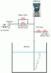
Following a request from a customer, Yokogawa has carried out an investigation into whether this diagnostic technique could be used for purge level measurements. The configuration used (Fig 5) was based on a 20 mm diameter dip pipe with a tip angle of 60° and an air flow set at 15 litres per hour. (In this set-up, a block valve is used in addition to the needle valve since the needle valve does not fully close or fully open.)
Dip tube diagnostics or purge level measurements use a constant air flow to determine the level in the vessel. Essentially this level creates a back pressure that can be measured at the transmitter and changes according to the level in the vessel; increasing the level also increases the resistance or back pressure. Using impulse line blocking diagnostics, it has proved possible to detect the bubbles breaking off the end of the dip pipe, thereby confirming that the system is still operational. A further advantage is the system’s ability to detect the noise resulting from any leakage in the system, which is then accompanied by a pressure drop. The use of different levels in these tests confirms that detection of either a leak or blockage can be achieved irrespective of any changes in level.
Conclusion
Users of differential flow transmitters need to receive diagnostic information before a line block leads to a malfunction. The techniques described provide predictive diagnostics based on trend analysis of the blocking factor, improving maintenance efficiency.
Impulse-line blocking diagnosis based on these techniques offers a number of benefits by informing operators and maintenance engineers that a blockage is forming in an impulse line before the process is disrupted. It can also be used to predict when the impulse line will be blocked and suggest corrective action, based on blockage thresholds. Moreover, realistic blockage thresholds are determined based on blocking substance, flow-rate variation, and the time required for taking corrective action.
Differential pressure flow measurement provides a reliable, accurate and economical solution. The long-standing problem of impulse-line blocking is now being tackled using intelligent impulse line blockage detection. While impulse-line blocking diagnosis is affected by a number of environmental factors, including piping vibration and noises, flow disturbances etc., impulse-line blocking diagnosis can eliminate the effect of such disturbances. The techniques used for impulse-line blocking diagnosis are being extended to confirming the validity of purge level (‘dip tube’) fluid measurements.

